


|
|
|
|||||||
| Последние сообщения на форуме |
| Последние комментарии к фото |
| Новые записи в дневниках |
| Новые комментарии в дневниках |
| Новое в группах |
| Ссылки сообщества |
| Социальные группы |
| Поиск по форуму |
| Поиск по метке |
| Расширенный поиск |
| Найти все посты, за которые поблагодарили |
| К странице... |
|
#1
|
|
Practical railway engineering. Track The origin and development of railway track Before the beginning of the eighteenth century, wheeled transport was generally hauled by horse and ran on surfaces which at the best was reinforced by a broken stone foundation and at the worst was simply a mud track. It was found at a very early stage of the development of land transport, that most road surfaces and foundations were very quickly damaged by heavy wagons on rigid wheels. The first railway tracks were laid down in the eighteenth century for horse drawn trains of wagons in collieries and quarries. These ‘hauling ways’ initially had a surface of stone slabs or timber baulks which proved unsatisfactory as loads grew heavier. As the Industrial Revolution progressed, the idea was developed further by adding wrought iron plates to reduce wear on the wooden baulks. This evolved further first to cast iron plates and later to edge rails, enabling for the first time the use of flanged iron wheels. By the time locomotives came on the scene in the early nineteenth century, wrought iron rails had developed further and became strong enough to support these heavy engines without assistance from longitudinal timbers. In 1825, the Stockton and Darlington Railway was constructed adopting track of wrought iron rails resting in cast iron chairs supported on stone blocks set in the ground at three feet intervals. The rails were of‘T’ section 15 feet long and weighed about 28 lbs per yard. As experience was gained and new technology evolved, rails steadily increased in size, both in length and cross section, and were made in steel rather than iron. Early railways evolved the ‘bullhead’ or dumbbell section of rail which was standard throughout the UK up to the Second World War. This rail was manufactured in increasing lengths and heavier sections and by the early 1900’s had been generally standardised to 60 foot lengths and about 95 lbs per yard weight. Most railways today use flat-bottomed rail. The individual stone block sleepers were early found to be unwieldy and unsatisfactory from several points of view, largely relating to weight and the lack of tying of rails at a fixed gauge. These blocks were quickly replaced by timber cross sleepers which proved to be much more economic and satisfactory. Cross sleepers, or ‘ties’ as they are known in some countries, have been generally adopted world-wide and are now often manufactured in concrete or steel although timber is still used extensively. At a very early stage, the need for good preservation of softwood left in wet ballast became very obvious. By the 1880’s, several railway companies had set up their own plants to impregnate sleepers with creosote under pressure. Basic components of track Today most railways have rolling stock with hard steel flanged wheels running on two rails set at or about 1432 mm standard gauge, supported in some way to spread loads to the ground below. ‘Sub-grade’ is the term used for the natural soil stratum, or embankment soil, after trimming off organic topsoil and made ground, upon which the track bed is constructed. The ‘Trackbed’ comprises the ballast and any sub-ballast layers and is there to support the track, to drain water from the bottom of the sleepers and to distribute the imposed track load to such a degree that the sub-grade can resist the imposed bearing pressure adequately. Track ballast Early railway engineers did not at first realise the important engineering function carried out by the ballast, as outlined above. Because of this all manner of material was used beneath the sleepers which today would be considered completely unsuitable. This included materials which would be cheaply and easily available locally such as ashes, chalk and clay. Experience soon showed that good quality ballast, made of well graded gravel, crushed gravel, limestone or igneous rock was necessary if adequate foundation and good drainage is to be achieved for a reasonable period. Today, the required depth of good quality ballast beneath sleepers varies depending upon the maximum speed of trains, the maximum axle loads carried and the gross annual tonnage expected. In general, the absolute minimum depth of ballast needed beneath sleepers for even a lightly loaded railway should never be less than 150 mm and heavily loaded main lines can require as much as 280 mm. The currently recommended minimum thicknesses of ballast beneath sleepers for lines in the UK are as shown in Fig. 5.2 below. To ensure both lateral and longitudinal stability of the track, particularly when using continuously welded rail, it is essential that ballast is taken up to the level of the top of the sleepers between the sleepers and given a good ‘shoulder’ at the sleeper ends. Materials for track ballast Good quality track ballast is made from crushed natural rock with particles not larger than 50 mm or generally smaller than 28 mm. Angular stones are preferable to naturally rounded stones, to achieve the best interlock properties and resistance to longitudinal and lateral movement under dynamic loading. If ballast particles are larger than the maximum size stated, there may only be two or three stones between the underside of the sleeper and the sub-grade will be insufficient to properly distribute the load. Too many small stones below 28 mm will however clog the ballast and reduce, in the longer term, its drainage properties. Samples of track ballast must be checked for grading by sieve analysis. Not more than 3% by weight should be retained on the 50 mm square mesh sieve and not more than 2% should pass through the 28 mm sieve. Ballast particles can suffer degradation due to the action of traffic and maintenance operations in broadly two ways. Either edges can become rounded and lose their interlocking effect or particles can break or crush under repeated loading. Some of the softer stones suffer badly from attrition in the presence of water. This deterioration, particularly at rail joints, can be associated with ‘wet spots’ in the track which can cause rapid deterioration of line, level and riding comfort. Certain tests can be introduced to check the wet attrition qualities of ballast. Generally speaking, limestones tend to have poor wet attrition qualities, crushed granite being one of the best, although expensive. Sleeper functions Sleepers and bearers or timbers (for points and crossings) need to fulfil the following basic functions: 1. Spread wheel loads to ballast 2. Hold rails to gauge and inclination 3. Transmit lateral and longitudinal forces 4. Insulate rails electrically 5. Provide a base for rail seats and fastenings Sleepers are also often called upon to fulfil other secondary but important functions which should not be overlooked. These include: 1. Supporting wheels and/or jacks direct (in a derailment situation) 2. Acting as transverse beams when sitting on temporary ‘waybeams’ 3. Supporting signal engineering and other safety related equipment (such as trip cocks and point motors) 4. Supporting conductor rails, electrical bonds and feeder cables 5. Reducing noise and vibration on non-ballasted bridge decks Timber sleepers The traditional timber sleeper was accepted by most railways as standard up to about the middle of the twentieth century, although its durability limitations were recognised. Even today there are still many railways using timber sleepers, where the advantages of good resilience, ease of handling, adaptability to non-standard situations or electrical insulation are very important. Timber sleepers and bearers for surface railways are usually made of softwood, either imported Douglas Fir or homegrown Scots Pine. The standard dimensions for softwood sleepers used in the UK are 254 mm. wide by 127 mm. thick in cross-section by 2600 mm. long. All softwoods used in sleepers and bearers must be thoroughly seasoned and then impregnated under pressure with a suitable preservative before use. Traditionally, this preservative has been hot creosote but other materials have been used successfully in recent years which may have less associated health hazards. Main line surface railways are now progressively converting their important lines to prestressed concrete sleepers, which are described later. All lines in deep tube tunnels or in locations where fire could be a risk, are provided with sleepers and pitblocks made from imported untreated hardwood such as Jarrah. Jarrah timbers used on the surface for points and crossing work which is not protected from the weather can last up to 35 years. In the protected environment of dry tube tunnels, Jarrah sleepers on the London Underground have been known to last in excess of 50 years before needing renewal. The author has in his possession a handsome polished jarrah pen and pencil box which bears the following interesting inscription under the lid: ‘This box is made from jarrah sleepers withdrawn from the London Tube railways after 54 years continuous service. It is estimated that during this time 500 million passengers travelled over the sleepers.’ Such comment speaks for itself. Hardwood sleepers eventually usually need replacing after this long period not because the general condition of the timber has deteriorated but because it is by then not possible to get a sound fixing for chair screws. Softwood treated sleepers on the surface can be expected to last between 15 and 25 years depending on location and traffic use. Renewal is usually required because bad splitting and/or rot has occurred. Prestressed concrete sleepers (Monobloc) As a substitute to softwood, some experimental work was carried out during the late 1930’s on concrete sleepers. Originally, ordinary reinforced concrete was used but not found very satisfactory for a number of reasons. At that stage, concrete simply replaced timber, bullhead rails and cast iron chairs being used as in other conventional track. After the Second World War, prestressed concrete was developed and used extensively on new structures. The great advantage of prestressed concrete was that concrete is kept under compression under all conditions of flexure, both under load and after. This means that tension cracks do not occur which can allow ingress of moisture and corrosion of embedded steel. Development of prestressed sleepers took place about the same time as development of flat bottomed rail and direct fastenings. At the time of writing, the standard sleeper for main line railways in the UK is the F27(ASorBS) prestressed concrete sleeper manufactured by the pretensioned method. In this method, the prestressing tendons are tensioned prior to the concrete being placed and are only released once the concrete has reached sufficient compressive strength to resist the induced forces thus They have been shown to be completely satisfactory however in sidings and depots. Electrical insulation is necessary at fastenings if track circuits are being used for train detection and this is not always a simple or effective matter. In some climates, the normal coating of millscale and rust is sufficient to protect against significant loss of section by corrosion. Sleepers can however be given protection by dipping in bitumen or oil during the production process. Rail fastenings, baseplates and pads Early railways adopted various forms of cast iron chair which were fixed to the sleepers and in which rails sat, being held in position by hardwood wedges or ‘keys’. All railways which used bullhead section rail used fixings which were basically of this type. With the introduction of flat-bottomed rail starting in the late 1940’s, a new form of fastening had to evolve. The need was to design a resilient connection between rail and sleeper capable of resisting all forces induced by the passage of trains and by temperature and weather variations over a long period of time. It was soon found that too rigid fixings became loose under vibration and that some degree of elasticity was necessary to resist both creep and buckling. Maintenance of the clip clamping force on the rail foot or ‘toe load’ was soon realised as being of crucial importance in this respect. Since the 1940’s many FB rail resilient fasteners have been designed, manufactured and used throughout the world, with varying degrees of success. These fastenings can be grouped into three distinctive types. These types are as follows: • An elastic rail spike. This is driven into pre-drilled holes in sleepers and can be used with or without a steel or cast iron base plate. • A spring clip bearing on the foot of the rail held down by a nut and bolt element tightened to a predetermined torque. This type of fastening is still used widely in France and Germany • A spring clip driven into a hole or slot in a ‘shoulder’ either cast into the sleeper or part of a base plate. The act of driving in the clip either twists or bends the clip thus creating a toe load on the rail. In the UK in recent years most railways, both main line and metro as well as some light railways, have gone for the last type when using FB rail. The standard fastening used by British Rail on all new FB track in recent years has been the Pandrol clip. This clip is made from circular section spring steel bar by a process which involves heating the bar, hot pressing into shape and then quenching and annealing. The majority of plain line track on BR is laid on concrete sleepers without base plates and in this case the anchorage shoulder is cast into the sleeper during manufacture. Where Pandrol rail clips are used in conjunction with base plates the latter are secured to the timber or sleeper by chair screws. Where DC electrified railways have conductor rails running close to running rails, it is necessary to ensure that rail clips can be placed and maintained without potential damage or dislocation of the conductor rails. With the Pandrol clip, this condition is satisfied as the clip is introduced into the shoulder and driven in a direction parallel to the running rail. Some earlier spring clips were driven at right angles to the rail which certainly would not be possible close to conductor rails. Fastenings require insulation both from electrical current and from vibration/noise. This is achieved by the introduction of resilient insulating pads at points of contact. Rails All modern railways use steel rails which are specifically rolled for the purpose from steel which has the required qualities of strength, fatigue endurance and wear and corrosion resistance. This type of steel is fully covered by British Standard Specification 11. As has been mentioned previously, the shape of the rail has now become generally standardised as the Flat-Bottom (FB) rail. This is sometimes known as the Vignoles rail, after the inventor. British Rail have now standardised on the BS113A section rail for all important lines. The head of the rail has an almost flat top with curves at the outer edges designed to fit the shape of the wheel tyre. One of the features of a well matched rail head and wheel tyre is that, when the axis of the wheel set coincides with the longitudinal axis of the track and the rail is set at its correct inclination of 1 in 20 to the vertical, the point of contact between the two is very close to the centre line of the rail. This is very desirable since it minimises the twisting effect on the rail which an eccentrically applied wheel load would produce, and by keeping the contact area away from the gauge comer, reduces both comer ‘shelling’ and fatigue damage. The rail head sides slope at 1 in 20. This is to compensate for the 1 in 20 inwards slope of the rails and not only makes it simpler to check the gauge but ensures that when side wear takes place the associated gauge widening is minimised. The thick web of the BS113A section is designed to give the rail adequate shear strength to guard against fatigue failures, particularly around fishbolt holes and under heavy axle loads at joints. The foot of the rail is broad enough to give stability against roll-over, remembering that steering forces exerted by rolling stock produce torsional and lateral forces which have to be resisted by the rail and transmitted via the fastenings to the sleeper. In addition to the primary function, the rail has secondary functions relating to the carrying of track circuit currents and in some cases on electrified railways, conveying return traction currents. Each section of rail that is used requires special steel castings, clips, bolts, resilient pads, fishplates, expansion switches etc. to make up the full structural system of the track. Most railway authorities endeavour to keep rail types and sizes to a minimum to ensure also that maintenance stocks of replacement components can also be kept to a sensible minimum. A great deal of capital can be tied up in stock which is kept in stores just to cover an eventuality which may never happen. There are also a number of signal related track components, like block joints, which are incorporated into the track structural system. With third and fourth rail DC electrification systems, there are also a large number of insulators and other fittings relating to the track which are required. Rail wear Abrasive wear occurs when there is contact between the side of the flange of a wheel and the gauge face of the rail. This contact usually takes place between the leading outer wheel of a vehicle bogey and the outer rail of a curve. On curves, careful periodic check must be carried out of the outer rail to ensure that side wear is kept within prescribed limits. Failure to do this could result in a derailment. Where curves are tighter than 200 m radius, continuous check rails should be provided inside the inner rail. This check rail is to be set not more than about 50 mm inside the running rail or at a distance that will ensure that the inside face of the flange of the inner wheels will bear on the check rail thus sharing the centrifugal force between the check rail and the outer rail through flange bearing. Abrasive wear of rails can be reduced by the use of rail lubricators placed at strategic positions. Great care needs to be exercised in the use of lubricators to ensure that only flanges are lubricated. Lubricant deposited on the top of rail heads can cause problems with braking, acceleration and wheel-spin. This is particularly important where trains are automatically driven or where stopping positions are critical such as when rolling stock doors have to line up with platform doors. When wheels run along fairly straight track with flanges just clear of the rails, the contact area between wheel and rail is extremely small. In theory the contact would only be a point which would make contact pressures infinitely high. In practice both surfaces deform slightly to give a contact ‘patch’. Even so typically such a patch has only an area of about 100 mm2, under the heaviest wheel load. This gives pressures as high as 1200 N/mm2 which is higher than the yield point of the steel. This has the effect of causing the contact patch to become plastic and to flow causing various wear patterns and irregularities over time. Where rails become side worn near to limit on curves, extra life can be obtained by either turning the high rail on jointed track or transposing the two rails on continuously welded rail. Close inspection of the existing inner rail outer edge must be carried out before transposing to ensure that there are no other defects present such as roll-over, ‘lipping’ or plastic flow that would make the ride rough and precipitate failure of the new running edge. If speeds in excess of 120 km/h (75 miles/h) are expected transposing should only be carried out if reprofiling of the existing inner rail is carried out. Wear on point and crossings needs to be carefully watched on a regular basis. Some repair of bad wear can be done by welding but in most cases components need to be changed. In jointed track, excessive wear often takes place at rail joints or fishbolt holes and is the main reason for rerailing. Joints also increase wear on rolling stock. This is one of the main reasons why main line railways are progressively changing to continuously welded rails. When a derailment occurs on any railway at any location, rail wear must be fully investigated as this can often prove to be the root cause. All rails should be closely inspected including any tell-tale signs of where wheels ran at the time of the derailment. 5ЛЗ The desirability of removing rail joints The earliest memories of many from childhood days relate to the ‘Clackerty-clack’ of steam railways. In those days every schoolboy knew that rails were sixty foot long and had to have fairly loose bolted joints so that the rails could expand in the hot weather and contract in the cold. Well understood also to the regular suburban commuter was the familiar sight from the carriage window of the platelayer driving in keys and greasing fishbolts. To many career railway men however these ‘chores’ represented a sizeable annual workload and removal of joints, if it could be done practically and safely, would be a giant leap forward. Apart from the reduction of potential track irregularities and smoothing and quietening down of the ride, removal of rail joints would clearly show a reduction of wear on wheels and rolling stock components in general. There would also be an improvement in the performance of underframe and bogie components subject to fatigue. Up to the outbreak of the Second World War in 1939, mechanical, civil, structural and marine engineers had all used bolting and rivetting as the main method of joining together steelwork in its various forms. During the War, metal arc welding began to be used for the first time and after the War welding began to be used extensively, particularly in structures, machines and ships. Introduction of track welding In the immediate post-war years, certain wartime teething troubles with metal arc welding were eventually ironed out and better understood, as wider experience was gained. In particular, failure of welds or the parent metal in the heat affected zone of welds by metal fatigue took some time to understand and correctly predict. These fatigue failures were particularly troublesome in some of the early welded ships and to a lesser extent in some welded bridge members. Metal arc welding was used extensively on steel structures in shop fabrication. By the late fifties, shop welding of this type had completely replaced the earlier shop rivetting of structures, site joints generally being site bolted or very infrequently, site welded. Although some metal arc welding and electroslag welding is used for the fabrication and repair of point and crossing work, the welding of rails end to end to form continuous welded rail (CWR) is carried out in the shops by a process known as Flash Butt Welding (FBW). Flash butt welding of rails commenced in the UK on a large scale in the late 1950’s and since that time, the process has been refined and improved but still remains basically the same. In the mid 1950’s, London Transport introduced flash butt long welded rails using the standard bullhead section. The FBW mils were produced by welding five standard sixty foot lengths into a long rail of 300 ft (about 90 m). These rails were joined using ‘tight’ bolted joints where the fishplates were clamped to the rail using high strength friction grip bolts, tightened to a predetermined torque. London Transport (LUL) are now in the process of changing over to flat-bottom rail. Main line railways in the UK use flat bottom section rail for CWR which is flash butt welded in the shops in lengths up to 240 m. In recent years in the UK British Steel PLC have been able to supply long lengths of rail already flash butt welded into long lengths. Shop welding to produce long rails The process of Flash Butt Welding is used in the shops to join rails which are later to be incorporated into Continuous Welded Rail sites. This process involves clamping the rails at a predetermined gap distance and passing a high current across the gap at a low voltage, during which the work pieces are brought together. Electrical resistance heating first causes contacting surface irregularities to melt and subsequently raises the temperature of the whole interface to near melting point. Once the components are sufficiently heated they are forged together, and excess molten steel at the interface is forced out of the weld area. The stages of FBW in the shops include burn off, preheating, flashing, forging and post weld treatment. Once the weld has solidified, integral shears at the welding plant remove the excess upset from the periphery of the weld, leaving about 1 mm proud all round the weld section. The welds are then straightened and the railhead ground to give a smooth profile for the weld along the length on the rail. Unlike metal arc welding, no electrodes or added metal is used, only the parent metal is fused. Because some of the metal at the rail ends is forced out of the section profile, the overall effective length of the rail reduces by about 20 mm for each weld. Site welding to produce CWR On arrival at site, long rails are welded to form CWR using the Thermit or alumino thermic welding process. This method, which was discovered in 1896 by Hans Goldmidt, is based on the reduction of heavy metal oxides by aluminium. Thermit welding was first used in Hungary in 1904 and most of Europe had adopted the process for site rail joints by the late 1920’s. The process was not used very widely in the UK however until the 1950’s. Some light railways have used Thermit welding of short rails throughout without the use of FBW into long rails beforehand. Although this is cheaper and removes the need for a shop process, the practice is not recommended for railways carrying heavy axle loads. Thermit welds are completely satisfactory but have less consistency than FBW, being carried out in the open on site rather than in controlled workshop conditions. Annual statistics, published on reported broken rails at welds in the UK over recent years, strongly bear out the better performance of FBW in practice. In this process, the rails to be joined are set in position, fixed in their baseplates, with the ends properly aligned and with a gap of 22-26 mm between them. A refractory mould is then placed around the joint and a thermit portion is ignited in a refractory crucible above the mould. The portion is a combination of powders which after reaction will produce a weld metal which matches the chemistry and metallurgy of the parent rails. When the reaction is complete, the crucible is tapped and steel pours into the moulds to form the weld. Slag, being less dense than the steel, remains at the top of the mould. The weld is allowed to cool after which the excess metal, mould material and slag is trimmed away and the joint is ground to profile. Stressing or ‘Locking-up’ of CWR With jointed short rails, the object is to allow rails to expand and contract during extremes of temperature to avoid the build up of compressive and tensile stresses. In long welded rails and CWR however, the rail is constrained so that it cannot expand or contract. In this case, in order that the rail shall remain at its original length, the rail undergoes compressive and tensile strain, which is equal and opposite to thermal strain. By simple calculation using Hooke’s Law, (F = strain X A x E), it can be seen that a restrained standard BS113A FB rail increased in temperature by say 45°C will produce a force of 76.5 tonnes in the rail. A compressive force of such magnitude in hot weather is sufficient to cause a buckle of the track and it is essential for safety that development of such a force is prevented. Similarly, high tensile forces in extremely cold weather can cause brittle fracture of rails and must be avoided. This is done on CWR by artificially extending the rail at the time of installation and fixing it down in a state of tension. The ideal is to fix the rail at a length that it will be, at a temperature that is exactly halfway between the hottest and coldest likely rail temperature. In the UK this is generally accepted as a temperature of 27°C. The rail may be artificially extended by rail wanning or, as is now more usual, by stretching with a tensor. Points, switches and crossings All railways require points or ‘turnouts’ to be able to divert trains from one track to another and crossings or ‘diamonds’ to allow trains to cross other tracks at an angle. This applies to all railways from the most complicated reversible layouts at terminal stations to simple single track tramways with passing loops. Any assembly of points and crossings is called a layout. Some layouts occur frequently and have acquired their own names. The most common is the ‘crossover’ which is simply two sets of points laid crossing to crossing in adjoining track enabling trains to change track in one direction. If two crossovers are superimposed, thus enabling movements from either track in either direction, the layout is known as a ‘scissors crossover’ for obvious reasons. In this layout there are four sets of points and one diamond. Points or turnouts and diamonds are themselves composed of elements known as crossings and switches. Crossing design and manufacture A crossing enables a wheel travelling along a given rail to pass through the rail of a track which crosses its path. Where two tracks cross each other at an angle, there are four crossings which make up the resulting diamond. Unless the tracks cross at right angles, there will be two Obtuse Crossings and two at an acute angle known as Common Crossings. ‘Built-up’ Crossings are manufactured from standard rail and are perhaps the most often seen, having been used traditionally on railways for many decades. In these crossings the four components, the point rail, the splice rail and two wing rails are cut, bent to shape, drilled and machined as necessary and then bolted together as a complete assembly. This type of simple crossing has given good service over many years in countries all round the world. They are subject to wear however, particularly at the tip of the point rail and where the point and splice rail bear against one another. Through bolts also often work loose under traffic. A ‘part-welded’ crossing consists essentially of the same four rails as a built-up crossing and is usually made of standard rail. The assembly however is strong enough to take thermal loads and consequently it can be welded into CWR, leaving only the flange way gap as a source of wheel/rail impact. In theory at least, this is a considerable advantage over both built-up crossings and cast crossings, although welding in of components into point and crossing layouts can have a significant time disadvantage when work becomes necessary during possession. The ‘Vee’ of a part welded crossing is prepared by machining two pieces of rail into a symmetrical straight splice with a weld preparation milled into the head and foot. The electroslag welding process is used under carefully controlled conditions to produce a continuous homogeneous weld. This welding is laid down automatically with top and bottom welds being done simultaneously to keep any distortion to an absolute minimum. The complete crossing assembly is held together using high strength friction grip bolts tightened to a specified torque or by ‘huck’ bolts. Another form of crossing is the cast Austenitic Manganese Steel (or AMS) crossing. In this case there is only one ‘monobloc’ component making up the entire casting. The casting is made by pouring this special molten steel into a mould which represents the shape of all four components used in the other types of crossing. This type of crossing is favoured by many railways due to its very high wear resistance and long life. Also due to being monolithic, there is no relative movement of components and the ride is generally very good. Another advantage is the ability to combine more than one crossing in a single casting, as is sometimes the case on a tight scissors crossover. In spite of its advantages however, AMS crossings do have some disadvantages. Casting as a process is always subject to internal cracking due to cooling and these faults are sometimes difficult to detect before installation. Also when faults do arise in service, the castings are much heavier and more unwieldy to handle during a limited possession than built-up crossings, particularly in tunnel. Check rails are provided opposite crossings. Their function is to control the alignment of the wheelset so that it is not possible for the wheel moving across the gap in the throat of the crossing to strike the nose of the crossing or to take a wrong path. Points or turnouts Points or turnouts, as shown below, enable vehicles to be diverted from one track to another and consist of a pair of switches and a crossing, connected by closure rails. In a set of points the fixed rails on either side are known as stock rails, the moveable rail being known as the switch rail. The switch rail is machined to a sharp tip or toe at one end and the tapered portion of the switch rail is known as the switch tongue. The switch tongue is machined to fit snugly into the stock rail in the workshops. It is unwise, when worn to change a stock or switch on its own and both should be changed as a fitting pair. Two movable switches should be held in the correct relative position to each other by at least two stretcher bars. If the set of points is so arranged that in the predominating traffic direction the tracks diverge, it is known as facing points. If the main traffic direction is such that the two lines merge, they are trailing points. 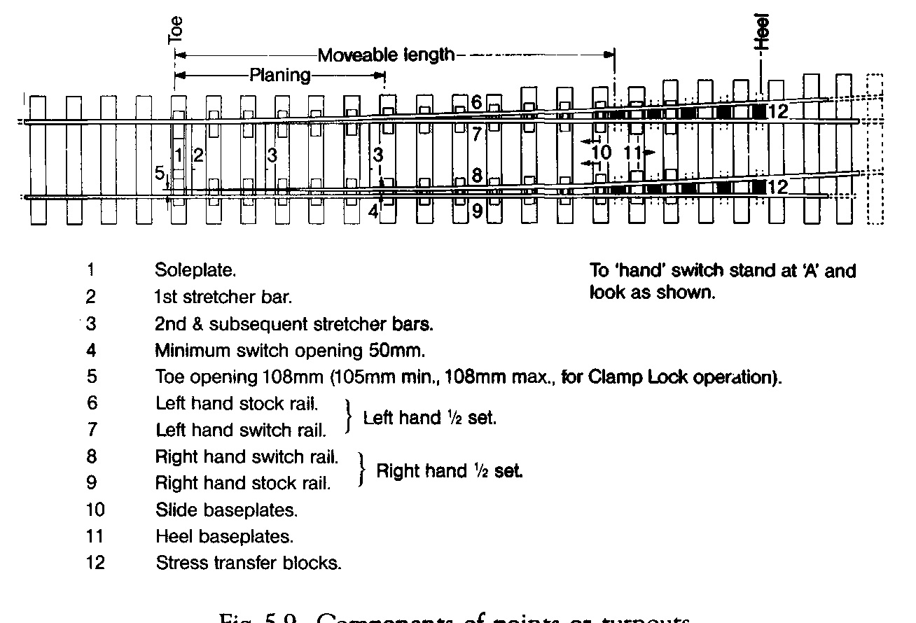 Driving, locking and detection of points In the early days of railways, sets of facing points on passenger lines were avoided because of the high risk of derailment due to wheel flanges ‘splitting’ stocks and switches. Following this early experience, it became mandatory that all facing points should be locked in position and that the position of each switch should be ‘detected’ in relation to its mating stock rail. On modem railways, points are operated by electric or compressed air point motors/machines which operate the points, lock and clamp them in position and also detect whether or not the switches are fully ‘home’. There needs to be careful and clear division of responsibility for maintenance and adjustment of all point mechanisms between signal and track engineers. Conductor rails and components Where railways are electrified using either third rail or fourth rail DC systems there are a number of other components and fittings which are track related. Conductor rails are usually made from steel which is designed to be of high electrical conductivity, containing much less carbon than for normal rails. This means that steel conductor rails are softer and of lower strength than running rails. The rails can be jointed by bolted fishplates or welded. In recent years, some light rail systems e.g. DLR, have used Aluminium conductor rails for underside contact, with a wearing surface of stainless steel. Conductor rails are supported by insulators fixed to sleepers at frequencies depending on track curvature, location and type of fixing. The insulator assembly usually consists of a porcelain pot with a cast malleable iron cap having two upstanding ‘ears’. These ears locate the conductor rail transversely without restraining longitudinal movement. The insulators are fixed to the sleeper using a pair of wrap round base clips. At discontinuities and ends of conductor rails, ramps are provided, also supported on sleepers, to pick up and lower collector shoes on rolling stock. It is important that these ramps, which can be welded steel or cast iron are regularly checked to ensure that line and level is correct. Failure to do this can result in damage to rolling stock or track or both. Paved concrete track Paved Concrete Track (sometimes known as PACT) is a continuously reinforced concrete pavement laid by a specially designed ‘slip-form’ paver. This machine runs on accurately positioned guide rails which ensures that the concrete pavement line and level is very closely controlled. The guide rails are often the long welded rails which will subsequently be repositioned and used as permanent running rails. The rails are usually supported on baseplates which may have some form of resilience incorporated into their design. Even though the concrete has been accurately positioned, the tolerances achieved may be more than is desirable for accurate positioning of the rails. It is desirable therefore that some adjustment capability is built into the system of final positioning of the baseplates or cast-in fixings. One way of achieving this is for the rails to be finally positioned to line and level on temporary packs/wedges with baseplates and fixing bolts hanging off the rail. Once final rail position is fixed, any gaps at fixing holes and under baseplates can then be grouted up or filled using epoxy mortar. This track system is much more expensive than conventional ballasted track and cannot be easily modified once laid. It is however of particular use in existing main line size tunnels, where the shallow construction depth may permit the achievement of increased overhead clearances for 25 kV electrification or for the passage of large container trains. In this track system particular attention needs to be given to drainage channels. As a cheaper alternative to PACT, prestressed or reinforced concrete sleepers or special purpose made units can be laid in position accurately with rails fully adjusted and then a concrete slab poured between and around them. In this case, holes through the sleepers are left for transverse reinforcement or some ‘hedgehog’ starter bars are provided to assist both the precast and iri'situ elements to act as a whole. Floating slab track In locations where it is vitally important to reduce noise and vibration to an absolute minimum, floating slab track may be considered. It should be stressed that this type of solution is very expensive, requires a lot of space and can only be justified where railways run very close to or under concert halls, churches or operating theatres etc. In this form of construction the trackform , which may be ballasted or non-ballasted, is supported on a structure which is isolated from the supporting ground by soft resilient bearings. A notable example of this type of construction is to be found in London under the new Barbican Concert Hall. Track installation and renewal Up to the late 1930’s most railways installed or renewed track mainly ‘piece-small’, using a large amount of skilled labour, only assisted for heavy lifts by rail mounted steam cranes. In more recent years, special ‘purpose-built’ equipment has been produced, in particular for surface main lines which mechanizes much of the track laying process. Large machines can now lay panels of sleepered track or place individual sleepers, to be followed by plant laying welded rails in very long lengths. Because of space restrictions in tube and other small bore tunnels, much of the laying of tracks in these tunnels is still carried out piece-small, using manual methods but using power tools and aids wherever possible. This has the added complication in tube tunnels that night possessions for renewal work are short and track has to be made safe each morning for a further day’s running. Day-to-day maintenance of track The passage of trains coupled with the effects of varied weather and day/ night conditions, causes steady deterioration of even the best constructed railway track unless proper day-to-day maintenance is carried out. Activities of others alongside the railway and trespassers and vandals on the railway can also effect track conditions of safety. Both visual inspection of condition and mechanical measurement of track geometry is necessary to establish a quality standard and to determine whether the standard is being maintained or not. All railways require a track maintenance organisation to ensure adequate inspection is carried out and that proper resources are available to attend to minor matters on the track and immediate surroundings as they arise. On surface lines, where it is possible to safely stand to one side to allow trains to pass, much daily inspection and local adjustment can be carried out during traffic hours. On underground railways or other urban railways where clearances are tight and trains are frequent, access for staff is not usually available during traffic hours. In this case maintenance staff must be organised to be on duty at night during non-traffic hours. For these railways all inspection and adjustment of track must be done at night and cannot be watched or further adjusted during the following day except under special protection arrangements which will inevitably delay trains. Regular major maintenance activities which will obstruct traffic or endanger staff, need to be arranged during non-traffic hours or in a ‘possession’ of the track specifically arranged for the purpose. Such major activities might well include ballast tamping, drain rodding, rubbish clearing, block joint changing, fence repairs close to the track and replacing individual damaged sleepers, chair castings or rails. Further Reading More detailed information on track may be found in ‘British Railway Track’, Sixth Edition 1993, published by The Permanent Way Institution. |
|
|
||||
| Тема | Автор | Раздел | Ответов | Последнее сообщение |
| =Книги= Bonnett C.F. - Practical Railway Engineering | Admin | Книги и журналы | 0 | 22.11.2014 16:24 |
| Practical railway engineering. Depots and Workshops | Admin | Wiki | 0 | 22.11.2014 12:21 |
| Practical railway engineering. Rolling Stock | Admin | Wiki | 0 | 02.07.2013 06:12 |
| Practical railway engineering. Station Layout | Admin | Wiki | 0 | 01.07.2013 19:58 |
| Practical railway engineering. Introduction | Admin | Wiki | 0 | 01.07.2013 19:47 |
| Здесь присутствуют: 1 (пользователей: 0 , гостей: 1) | |
|
|


