


|
|
|
|
#1 (ссылка) |
|
Crow indian


Регистрация: 21.02.2009
Возраст: 41
Сообщений: 30,409
Поблагодарил: 398 раз(а)
Поблагодарили 6046 раз(а)
Фотоальбомы:
2624 фото
Записей в дневнике: 904
Репутация: 126146
|
Тема: Diagnostic system for electric locomotive 2ES6 "SINARA"Diagnostic system for electric locomotive 2ES6 "SINARA" I.A. OSINTSEV, teacher of the Taiga division of the West Siberian Training Center for Professional Qualifications One of the advantages of microprocessor control systems (MPCS) is the possibility of continuous diagnostics in real time, i.e. analyzing the operation of equipment, determining the causes of malfunctions, modeling ongoing processes, predicting their development. The main objects of diagnostics on the 2ES6 Sinara DC electric locomotive are traction and auxiliary equipment, control system, auxiliary power converter (ASC), on-board power supply system, braking equipment (Fig. 1). The driver’s control activity is also considered as a separate diagnostic object. 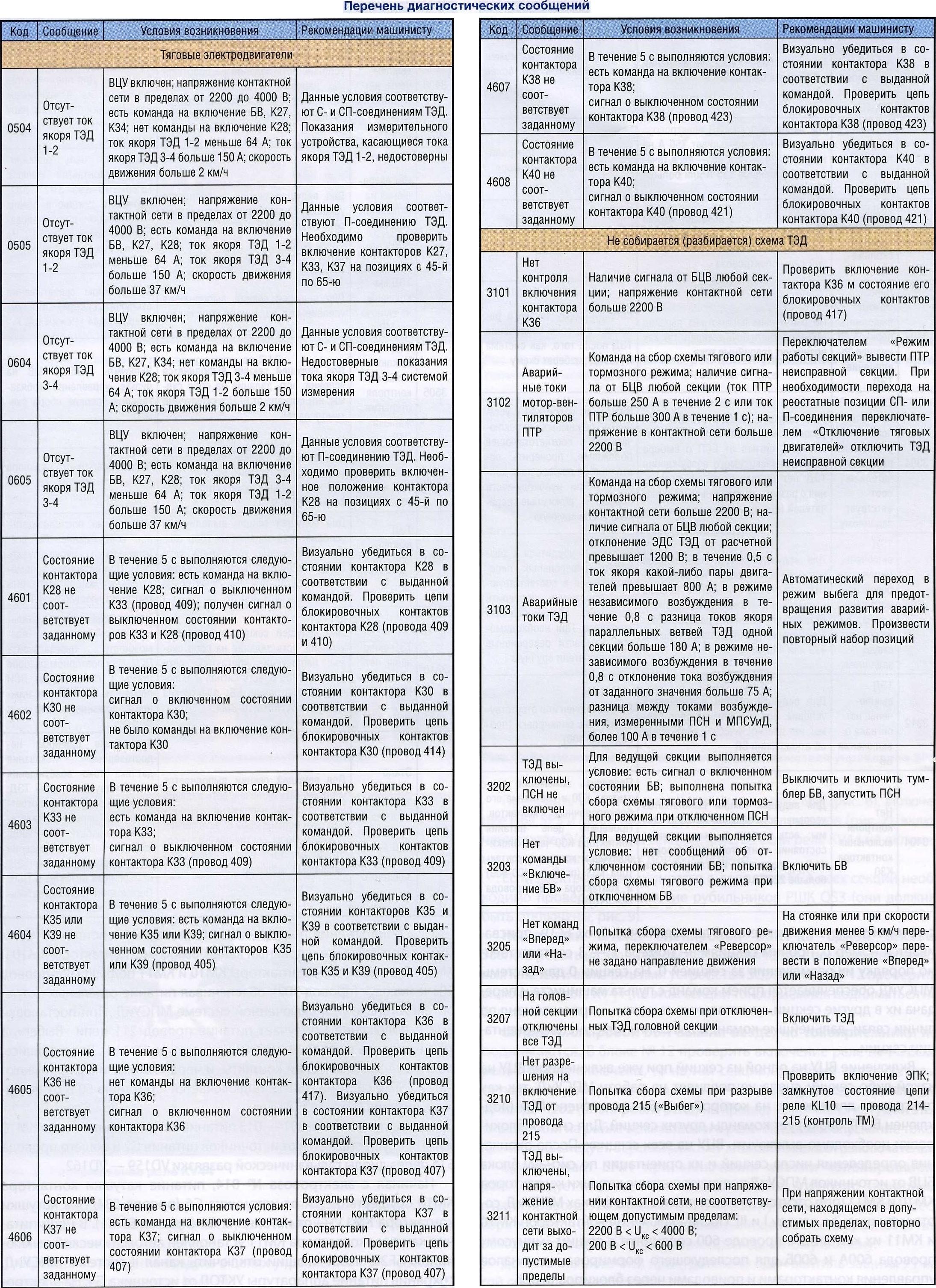 All information collected on the electric locomotive and involved in the operation of the control system is continuously diagnosed in parallel by a microprocessor control and diagnostic system (MPSUiD), which is made on the same equipment as the MPSU. Continuous analysis of processes and modeling of equipment operation make it possible to identify the following diagnostic events:
 Diagnostics are carried out during pre-trip checks, during the trip to analyze the operation of the equipment, during the repair process and after it to assess the condition of the equipment. The diagnostic results transferred from the electric locomotive to the server can be used by both repair and management personnel. For the driver, they, as well as recommendations for troubleshooting equipment faults, are displayed on the monitor screen in the “Driver” mode (in the diagnostic message line). The diagnostic message can be transmitted over radio channels and recorded in the archive. The list of diagnostic messages transferred to the archive is displayed in the “Diagnostic messages archive” information window. The number of active diagnostic messages in the archive is shown in numbers in brackets after the message text. The color of the indicator (cell with the letter “D”) of the diagnostic message indicates operating restrictions:
CONTROL SWITCH CIRCUIT Execution of all commands begins after switch S1 “Control circuit switch” (CCS) is moved from position III to position II or I, after which all previously entered commands are ignored, and commands from the previously included controls of the driver’s console (SB15 - SB18 “Pantograph”, SB3O “Quick Switch”, SB28 “Fans”, SB27 “Compressors”, SB11 “Forced Compressor Start”, SB13 “Tank Blowing”, SB47 “Brake Release”, SB35 “Sand”) are blocked (Fig. 2). Controls are also blocked when the VCU key is moved from position II to position I or vice versa, which does not allow the commands corresponding to the switches to be executed before they are unlocked. To unlock the switches, you must turn them off and then turn them back on. 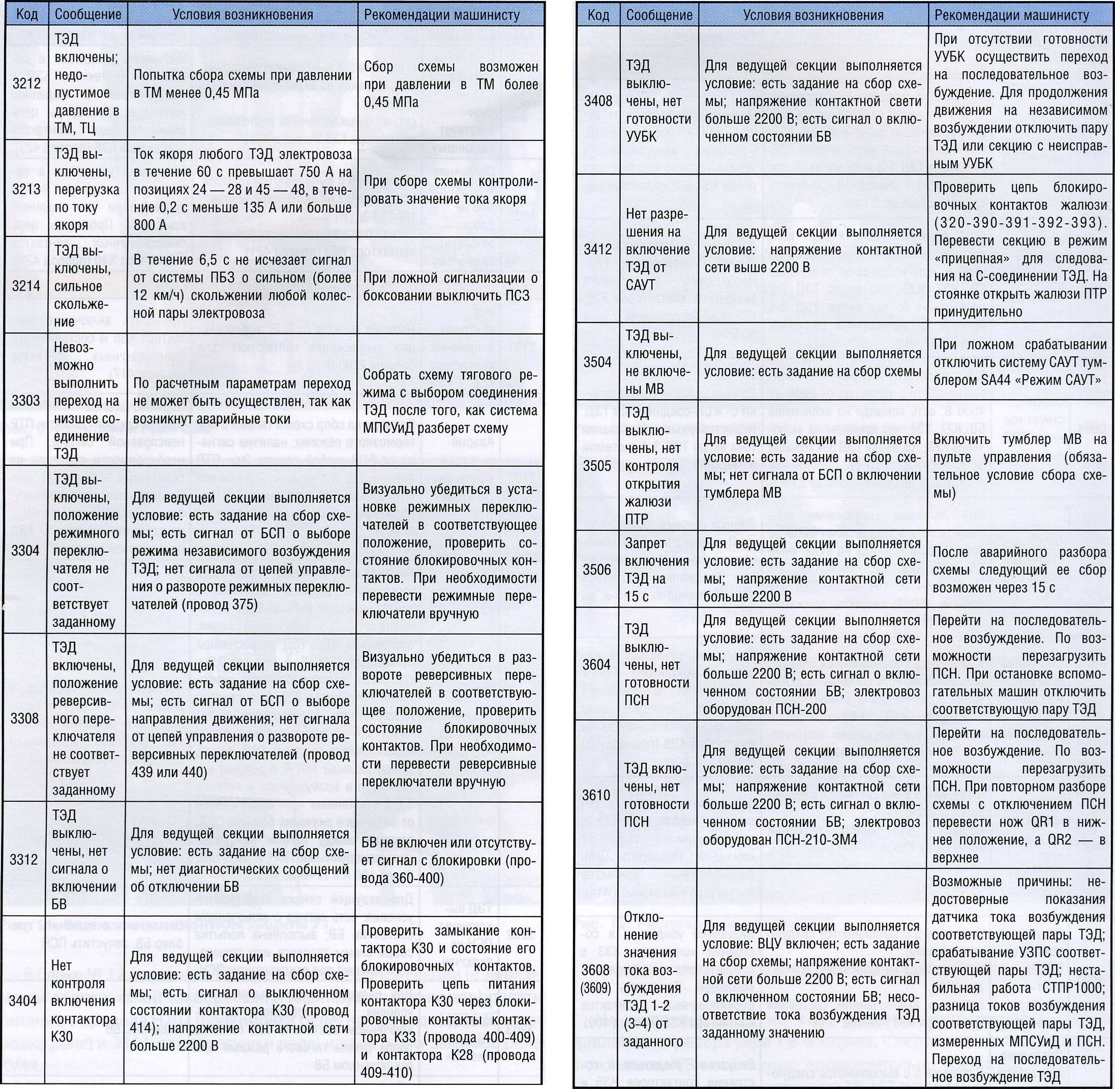 After moving the control circuit switch from position III to position I (contact group 11-12) or II (contact group 13-14), the GND wire on the section from which control is carried out (where the VCU is turned on) is connected to the BSP block (the BSP is turned on ), based on the signal of which the BCV block determines the number of sections and their orientation. For each section, its number is set: the section from which control is carried out (where the BSP unit is connected) is assigned number 0, other sections are given numbers 1 - 3 according to the order of their placement behind section 0. Section 0 for the MPSUiD system ensures that commands are received from the remote control the driver and transmitting them to other sections, in the remaining sections - receiving commands via the communication line, further commands are executed taking into account the orientation of the section. Turning on the VCU on one of the sections while the VCU on any section of the coupling is already turned on will not affect the operation of the MPSUiD, since the program for the section on which the VCU was already turned on (the BSP is connected) blocks commands from other sections. To remove the blocking, it is necessary to turn off the VCU on all sections. After determining the number of sections and their orientation, the coils of the contactors KM10 and KM11 are powered by the signal from the BCV unit from the MPSUiD sources (in the absence of faults in the MPSUiD units, respectively, via channel I and II). After switching on the contactors KM10 and KM11, their contacts in wire 600 are connected to the common “minus” of wires 600A and 600B for the subsequent formation of control channels for contactors and drives through BUK interlocks. If faults are detected in the BUK units, the MPSUiD system can disconnect the faulty channel by turning off the contactors KM10 and KM11. At the same time, contactors KM10 and KM11 connect wire 301 to the “plus” (wire 302), providing power to individual consumers only when the MPSUiD system is turned on. When the VCU is set to position I, wire 211 of the “Rundown” circuit, as well as relay coil KL14 (on electric locomotives up to No. 114), receives power. Having turned on, the KL14 relay closes its contacts, and through the SF24 circuit breaker the SVL-TR system is connected to a 50 V power supply from the G1 power source. 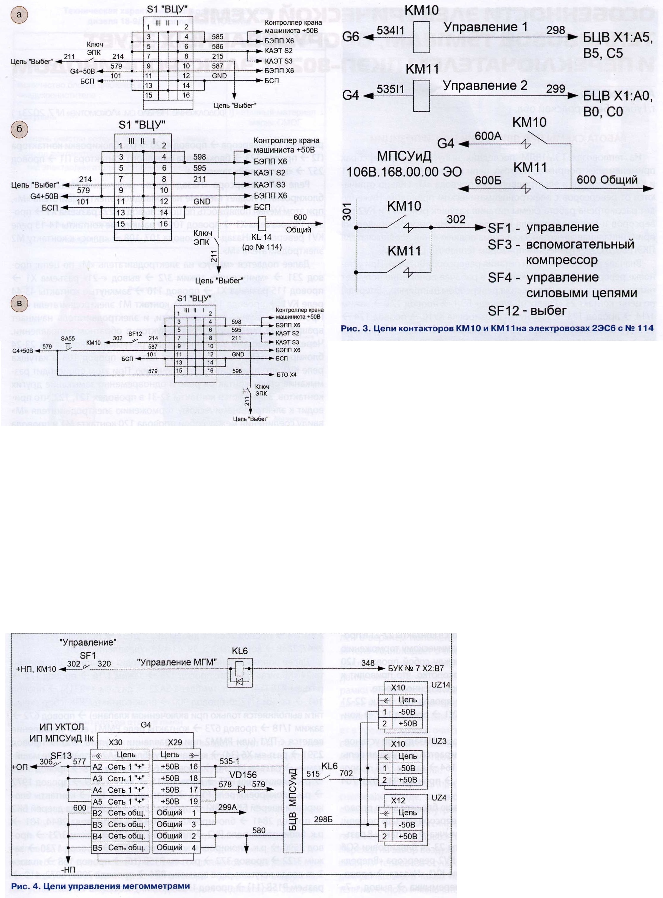 On electric locomotives No. 001 - 013, the contactor coils KM10 and KM11 are powered from power sources G2 and common wire 514 through galvanic isolation diodes VD159 - VD162. Starting from electric locomotive No. 014, the KM 10 contactor coil is powered from source G6 (wire 534/1), and the KM11 contactor coil is powered from source G4 (wire 535/1). An SF29 automatic switch is installed in the power supply circuit of the KM11 contactor coil, which allows you to turn off channel II of the MPSUiD system, while maintaining power to the UKTOL equipment from the G4 source. On electric locomotives with No. 017 and higher, the SF29 circuit breaker is not used. On electric locomotives with No. 114, reverse current diodes VD119 and VD120 have been eliminated in the coil circuit of contactors KM 10 and KM11 (Fig. 3). When transferring the VCU from position I to position II, the devices and control circuits of the electric locomotive are turned off in the following order:
MEASURING THE INSULATION RESISTANCE OF TRACTION MOTORS AND PSN To measure the insulation resistance, meters (MGM megohm meters) UZ3 and UZ4 were introduced into the power circuits of the electric locomotive, which provide the driver with information about the insulation resistance between the armature winding and the traction motor housing, displayed on the monitor of the locomotive control panel. The +50 V power supply for meters UZ3 and UZ4 is supplied from the BCV unit of the MPSUiD system via relay contact KL6 in wire 515 (Fig. 4). If the BVS (wire 324) of each section received a signal to close the high-voltage chambers, the roof exit hatch and turn on the KL1 relay, as well as a signal to turn off the traction motors (there is no signal from the voltage converters to code UZ10 and UZ11 about the presence of current in the armature circuit) , BUK creates the power circuit for the KL6 relay coil (wire 348) in two ways: E> manually, when in the absence of a command to raise the pantographs (toggle switches SB15 - SB18 “Pantographs” are in the “Off” position) and there is a signal from the UZ1 converter about the voltage in the contact network being less than 2000 V, the SB33 “Turn on megohmmeters” button is pressed , the signal “Turning on megger” from the BSP enters the MPSUiD, and the BUK creates a power circuit for the relay coil KL6; E> automatically, when with the pantographs raised (one of the toggle switches SB15 - SB18 “Pantographs” is turned on) and a signal from the UZ1 converter about the voltage in the contact network is more than 2000 V, the MPSUiD system 5 s after turning off the traction motors at least once every 30 min for 95 s turns on relay KL6. On electric locomotives 2ES6, starting from No. 114, a UZ14 meter is installed to measure the insulation resistance in the PSN circuit. |
|
|
Цитировать 14 |
|
|
||||
| Тема | Автор | Раздел | Ответов | Последнее сообщение |
| = RW-Locomotive = Air supply system of diesel locomotive 2TE25KM | Admin | Article-RW | 0 | 10.12.2023 15:45 |
| = RW-Locomotive = Troubleshooting during operation of electric trains ES1(P), ES2G(P) "SWALLOW" | Admin | Article-RW | 0 | 10.12.2023 15:35 |
| = RW-Locomotive = "TMH- Electrotech " is mastering the production of new generators for the freight diesel locomotive ZTE30G | Admin | Article-RW | 0 | 10.12.2023 15:32 |
| =Распоряжение= № 300р от 14 февраля 2008 г. - Об утверждении стандарта ОАО "РЖД" "Организация технической учебы работников ОАО "РЖД". Общие положения" | Admin | 2005-2008 годы | 0 | 04.05.2014 02:20 |
| =Распоряжение= № 2117р от 22 октября 2012 г. - О внесении изменений в порядок применения осевых масел ИНТЕСМО марок "Л", "3", "С" И "В" | Admin | 2012 год | 0 | 05.01.2013 21:07 |
| Ответить в этой теме Перейти в раздел этой темы Translate to English |
| Здесь присутствуют: 1 (пользователей: 0 , гостей: 1) | |
|
|


