


|
|
|
|
#1 (ссылка) |
|
Crow indian


Регистрация: 21.02.2009
Возраст: 41
Сообщений: 30,409
Поблагодарил: 398 раз(а)
Поблагодарили 6046 раз(а)
Фотоальбомы:
2624 фото
Записей в дневнике: 904
Репутация: 126146
|
Тема: More once about diesel locomotive TE3 More once about diesel locomotive TE3 A.G. IOFFE, engineer, Moscow I read with interest the article by M.V. Egorova about TEZ diesel locomotives and their operation at the Likhobory locomotive depot in the Lokomotiv magazine No. 6, 2023. The opinion of a production worker is of great interest. The TEZ series of diesel locomotives is a turning point in the development of locomotive engineering. Until 1956, diesel locomotives were an alternative, specific type of traction, intended mainly for work in waterless areas: on the then Ashgabat railway, then on the roads of Kazakhstan, the Orenburg region and the North Caucasus. At that time, diesel locomotives were relatively low-powered and few in number. Steam locomotives remained the main type of traction. In 1956, a decision was made to transfer transport to electric and diesel traction. TEZ diesel locomotives were the first to be created to operate across the entire range of non-electrified railways, and were capable of replacing even the most powerful steam locomotives of the FD series. For such a large-scale reconstruction of traction in 1956, the construction of TEZ diesel locomotives was organized at once at three main former steam locomotive factories in Kharkov, Kolomna and Voroshilovgrad (Lugansk). The work was based on broad cooperation between factories. 2D100 diesel engines were produced in Kharkov and Kolomna, electric traction machines were produced at the Kharkov Diesel Electrical Equipment Plant (since 1959 - “Electrotyazhmash”), and the Lugansk plant became the leading plant for the crew parts. In the 1960s, TEZ diesel locomotives became the main ones on the network. The concepts of “diesel locomotive” and “TEZ” have become almost synonymous. In just two decades, 13,617 sections of only two-section TEZ diesel locomotives were produced. Both quantitatively and qualitatively, the TEZ diesel locomotive became the first truly mainline diesel locomotive, so it would be reckless to expect flawless operation from this locomotive. Veterans of the diesel locomotive department of VNIIZhT said that the TEZ diesel locomotive, despite its unprecedented mass production and the duration of construction, was never officially accepted into mass production due to many complaints about its design and the quality of components. How then can we explain the authority gained by TEZ diesel locomotives among movers and locomotive crews? First of all, this is “torque”. The machinists noted the fairly stable operation of the TEZ at speeds below the design speeds without slipping. For this, TEZ was called a “tenacious” locomotive. The second factor was the simplicity of the design, wide passages in the diesel room and the refrigerator shaft (Fig. 1 - 3). In cases of malfunctions, it was often possible to eliminate them on our own and without calling in an auxiliary locomotive. Even at the beginning of the 1980s, when the construction of diesel locomotives of the TEZ family was stopped long ago, these diesel locomotives were present in the fleet of all 32 railways of the USSR. It was the diesel locomotives of the TEZ series, which by that time were quite old, that were sent to areas with the most difficult operating conditions. TEZ diesel locomotives became one of the symbols of the BAM, where they opened traffic in many areas, serving in temporary operation departments (OVE). They worked both in Yamal and in coal mines in Western Siberia. 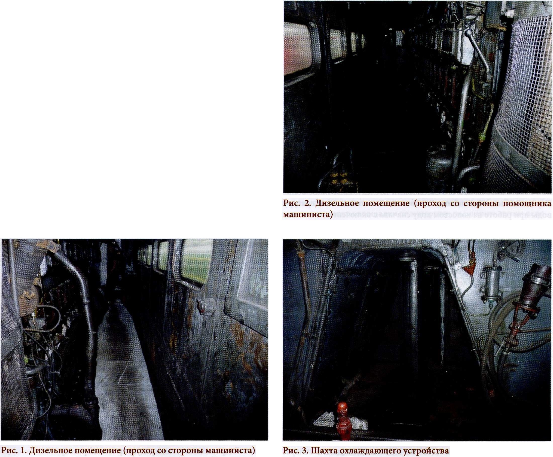 This series had a lot of flaws. Due to poor sound insulation, there was noise and drafts in the locomotive cabin. The suspension, especially on early production carts, was very stiff. The 2D100 diesel caused big problems. When creating the first diesel locomotive at the Kharkov plant, the design was based on the DA series locomotive of the American company ALCO. The four-stroke six-cylinder diesel engine with a power of 1000 hp is installed on it. had a proven design and was created specifically for diesel locomotives. This power plant, which received the name D50 in domestic production, was installed on diesel locomotives of the TE1 and then TE2 series. The TEZ diesel locomotive, designed to drive trains on the main railway lines, required a diesel engine that was twice as powerful. There were no diesel locomotive power plants of such power in the USSR. Therefore, when creating the 2D100 diesel engine, the marine two-stroke diesel engine of the American company Fairbanks Morse was taken as a basis. The reason for this choice was that these power plants were installed on ships supplied to the Soviet Union from the United States under the Lend-Lease program during the Second World War. There was already experience in operating, repairing this diesel engine and manufacturing a number of spare parts in the USSR. In terms of weight and dimensions, the power plant was suitable for use on a diesel locomotive. True, this diesel engine had a rather exotic design, with two crankshafts and counter-moving pistons. At the same time, it did not have a valve mechanism, cylinder covers, and did not require special grades of steel for its manufacture. This promised rapid organization of production. But during the development of production and operation of the 2D100 diesel engine, many difficulties arose. In addition to the shortcomings noted by the author of the article, I would like to especially highlight the need for such a labor-intensive operation as cleaning the exhaust windows of cylinder liners from carbon deposits, which had to be done through one TO-3. This drawback was inherited to an even greater extent by more modern TE10 diesel locomotives. Cleaning is done through the exhaust manifold covers. Due to the inclined arrangement of the channels of the exhaust boxes, windows have to be cleaned in an awkward position, especially on TEZ diesel locomotives converted to alkaline batteries, where the floors are made higher. Diesel locomotives often arrived at TO-3 with almost completely overgrown windows. Each of the ten cylinder liners had five windows on each side. Cleaning had to be done only on the piston heads, i.e. periodically it was necessary to manually turn the crankshaft to the desired position. Among the disadvantages of diesel engines listed by the author of the article, I would like to touch upon the topic of water leaving the system. Adapter bushing units for 2D100 diesel engines, as well as for 1 OD 100 engines still in operation today, have seals: annealed copper gaskets with a sleeve and rubber rings with a jacket. When the seals are in working condition, there is no significant water leakage. Water leaves when a crack appears in the liner or when the rubber seals become “tanned” as a result of overheating. It is also possible for water to escape after excessive hypothermia of the diesel engine, as the author of the article writes about. Here it is necessary to observe the temperature regime when the diesel engine is running, when it stops and then drains the water. Before stopping, it is necessary to gradually reduce the water temperature while idling, first with the fan on and then with the fan off. And only when the water temperature dropped to 40 - 50 °C, it was possible to stop the diesel engine, then crank the crankshaft and, if necessary, drain the water. The standard mentioned by the author of no more than 60 drops per minute refers to the dripping not along the adapter units, but along the water pump seal. The fact is that the water pumps of the D50 and D100 diesel engines do not have modern mechanical seals, such as those of the D40, D49, K6S310DR, 1-PD4D diesel engines, but gland seals. In order for the stuffing box to work properly, it must be cooled and lubricated by slight dripping. There is no such requirement for adapter nodes. On the contrary, when accepting a diesel locomotive from repair, there should be no water leakage. As for cases of peddling, this happens on diesel engines of all types. This is often caused by oil getting into the charge manifold. It is no coincidence that to combat this phenomenon, all diesel engines are equipped with limit switches, and many are equipped with additional air flaps that block the path of air into the cylinders. The author of the article mentions the modernization of TEZ diesel locomotives with the replacement of standard 2D100 diesel engines with 12D70 and 2D49 (diesel generator set 26DG). Such projects were indeed developed, and in 1972 - 1975. on experimental diesel locomotives they are embodied in metal. However, it is unlikely that these projects could be considered seriously in those years. Firstly, at that time TEZ diesel locomotives were discontinued, and the D70 and D49 diesel engines themselves were still in the development and development stage. They suffered massive scuffing of crankshaft bearings and many other malfunctions. Therefore, even if we assume the appearance of TEZ diesel locomotives with new diesel engines, this would result in a decrease in reliability rather than an increase in it. Secondly, the modernization of TEZ diesel locomotives carried out at that time was rather exploratory and partly advertising in nature. The new diesel engines D70 and D49 had difficulty making their way, and railway workers accepted them with obvious reluctance. Therefore, manufacturers sought to offer potential customers as many options for using their products as possible and, in addition to the main 16-cylinder modifications, also created power plants for use on other locomotives, with a different number of cylinders, power, crankshaft speed, with different options for traction generators, as well as for working with hydraulic transmission. Thirdly, even if we take into account the intensive work carried out on fine-tuning new diesel engines, the capabilities for their production were significantly inferior to the needs. At the Voroshilovgrad (Lugansk) Diesel Locomotive Plant alone, the annual production of mainline diesel locomotives in the 1970s and 1980s exceeded a thousand sections. Supplies of Kolomna diesel engines D49, even when their production was to a certain extent established, could cover these needs by less than a third, and the Kharkov plant actually curtailed work on the development of diesel locomotive diesel engines D70. Therefore, no one would devote a significant part of the production capacity of the Kolomna Plant to the production of diesel engines for the modernization of long-outdated TEZ diesel locomotives to the detriment of the construction of new powerful diesel locomotives 2TE116 and 2TE121. So the planned economy mentioned by the author has nothing to do with it. 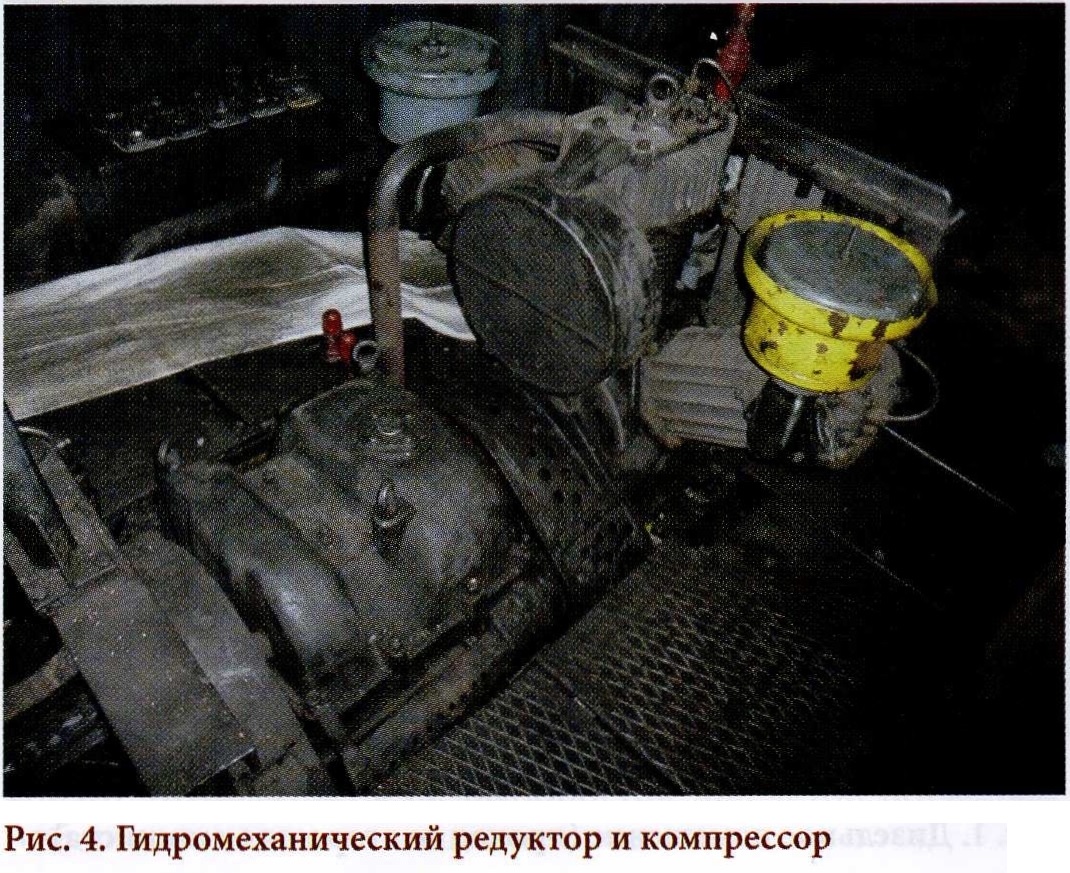 One cannot but agree with the author of the article regarding the operation of oil-air cooling sections. Back in the 1950s, experts came to the conclusion that radiator sections, when used to cool oil, operate unreliably and inefficiently. Most diesel locomotive plants introduced water-oil coolers (heat exchangers), but given the imminent discontinuation of TEZ diesel locomotives, they did not redesign their design. To preserve the oil sections, a bypass valve was introduced on the TEZ diesel locomotive. When starting a diesel engine after a long stay, so that the pressure of cold oil in the system does not “rupture” the oil sections, this valve should be opened. Then part of the oil flow was drained into the crankcase. Then, as the oil warmed up, this valve had to be gradually closed, and then closed completely. It happened that the assistant driver forgot about this valve, and a leak formed at the oil sections. As the author of the article accurately noted, the fan drive of the cooling device (refrigerator) caused a lot of trouble. The main reason for the failure of the shaft line parts was that on the TEZ diesel locomotive the hydraulic coupling, which operates as part of the hydromechanical gearbox (Fig. 4), is constantly filled with oil, and the fan is turned on and off by a friction clutch, which was used as the clutch of a ZIS vehicle ( Fig. 5), i.e. The process of turning on the fan is harsh, especially at high positions of the controller. When the positions are reset, the rotation of the crankshaft slows down sharply, and the massive fan wheel, which has high inertia, strives to maintain the selected rotation speed. Similar processes occur when recruiting positions. These shock torsional forces have a detrimental effect on the shaft parts and the friction clutch itself. A remarkable inventor, mechanic at the Likhobory depot Ivan Mikhailovich Pryakhin improved and simplified the design of the friction clutch, but this did not completely eliminate the problem. Many depots have developed local instructions requiring, for example, to turn off the fan before resetting positions, but this instruction was not always followed. It was especially bad if the diesel engine was stopped with the fan clutch engaged. All this reduced the service life of the shafting, and sometimes led to immediate breakdowns. Comparison of the reliability of shafting on diesel locomotives TEZ and on less powerful TE2 is not entirely objective. Although the diameter of the fan wheels on both series is the same (1600 mm), the fan on the TE2 diesel locomotive has six blades, and on the TEZ - eight, i.e. the fan is more massive, therefore, the inertia forces generated are greater. The rotation speed of the fan wheels is also different. At nominal mode, the TE2 diesel locomotive has a fan rotation speed of 985 rpm, and TEZ - 1020 rpm in winter mode and 1380 rpm in summer mode (the transition from one mode to another is carried out by switching the movable gear block in the hydromechanical gearbox, the end of the shift handle can even be seen in Fig. 4). In addition, TEZ diesel locomotives worked with full-weight trains, i.e. often at high controller positions. TE2 locomotives at that time were employed in auxiliary work, where they worked mainly in lower positions with lighter loads. An interesting question raised in the article concerns the compatibility of operation in a pair of sections of different TEZ diesel locomotives, i.e. acquisition of so-called “hybrids” or “pull-to-kai” into the depot. By the early 1980s, all diesel locomotives had gone through multiple factory overhauls, where the electrical circuits resulted in the most common variant. Therefore, the inconsistency of disparate sections of different diesel locomotives was mainly associated with depot reasons. Firstly, the seasoned diesel locomotives of TEZ were prone to such a disease as “earth”, i.e. to reduce insulation resistance in power and control circuits. If on a particular two-section diesel locomotive a decrease in insulation resistance occurs somewhere at one point, then this is imperceptible. However, if you try to connect such a section to another, where a breakdown to the housing also occurred, but at a different point, especially in the “positive” circuit, then in such a “hybrid” or “push-pull” the most incredible phenomena can occur, such as: as spontaneous activation of electrical devices. Of course, such a locomotive cannot be released onto the line. 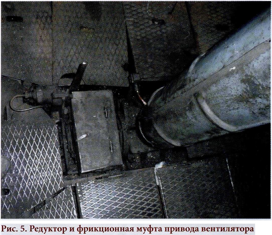 Secondly, incompatibility of electrical circuits on different diesel locomotives could arise, for example, when using backup wires to restore certain intersection circuits. On one diesel locomotive the same reserve wires could be used in some circuits, on another - in others. In addition, some of the diesel locomotives at the Likhobory depot were modernized during operation. On some diesel locomotives, a so-called parallel start-up scheme was implemented, when during the “scrolling” of the diesel crankshaft, the batteries of both sections on the “positive” side were connected in parallel through the main contact of the DZ contactor. On several diesel locomotives, a so-called generator starting system was introduced, when the starting winding of the traction generator of the section being started was powered from the terminals of the traction generator of the working section. Moreover, the connection diagrams were different. Naturally, a section on which one of the options for such modernization has been carried out cannot be coupled with a section that has another option. Diesel locomotives also differed in the control scheme of cooling devices. In the factory version, the control panel had four toggle switches: “left blinds”, “upper blinds”, “right blinds”, “fan clutch”. On the driven section, switching occurred synchronously with the leading one. It was a bad decision. Therefore, in depot conditions on many diesel locomotives, the control circuit wires were reconnected. One toggle switch was used to simultaneously open the left and right side blinds of the leading section, the second was used to open the upper blinds and turn on the fan. The remaining two toggle switches made similar switches on the slave section. It was not possible to combine sections with this modification and with the factory circuit. There was a reason for the possible “incompatibility” of different sections in pneumatics. Due to the large number and total volume of brake cylinders on locomotives, the air distributors do not act directly, but through a repeater, the role of which on the TEZ diesel locomotive is played by auxiliary brake valve No. 254. Initially, it was stipulated that on a two-section diesel locomotive the air distributor on only one section should be constantly turned on . To connect it with the auxiliary brake valve of the leading section, an impulse line with end valves and hose heads painted green passed through the locomotive. With the release of the new Instructions for the operation of rolling stock brakes TsT-TsV-TsL-VNIIZhT/277, the note to paragraph 3.2.7 prescribed the following: “For two-section locomotives, both sections of which are equipped with air distributors operating through valve No. 254, turn on both air distributors, the impulse line between sections is muffled.” This was intended to improve safety and increase the performance of automatic brakes. However, this transition dragged on for quite a long time. Therefore, the section of a diesel locomotive on which the impulse line was preserved and the air distributor was turned off could not be combined with the same section of another diesel locomotive. Thus, the possibility of creating so-called “push-pull” units from sections of different diesel locomotives was limited not so much by design restrictions as by the circumstances that arose at the depot. As for the creation of “hybrids” or “push-and-pull” from sections of TE2 diesel locomotives, this is a special question, if only because the sections of TE2 diesel locomotives were connected not by automatic couplers, but by rigid couplings, which made the very procedure of recoupling the sections labor-intensive, and without much effort there was no point in doing this. Some TE2 diesel locomotives operated in one section, and instead of rigid couplers, a so-called locomotive automatic coupler (an automatic coupler without draft gear) was installed on them at the rear. It was generally impossible to combine such a section with the section of a two-section diesel locomotive. The words of the author of the article about the fire-fighting installation installed instead of the boiler-heater also require clarification. The initially installed boiler-heaters were supposed to warm up the cooling water and lubricating oil during the cold season so that the diesel engine would not idle. However, a fan that forces air into the fuel combustion zone in boiler, consumed a lot of energy, intensively discharging the battery. As a result, after such warming up the diesel engine could not be started. Therefore, boiler heaters were not actually used, and subsequently they began to be dismantled from diesel locomotives. 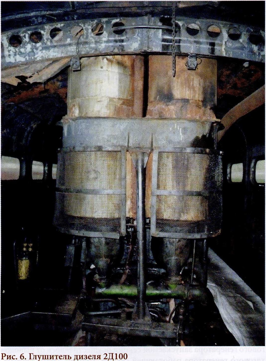 They decided to use the vacated space to place foam fire-fighting installations, which were considered progressive at that time. One of their advantages was that traces of foam after extinguishing a fire are easily removed, which cannot be said about more modern powder fire extinguishing systems. Moreover, these installations were installed on many diesel locomotives, and not just on TEZ. The main source of fires was possible exhaust gas breakdowns coupled with fuel and oil leaks. The areas where silencers were installed were especially fire hazardous (Fig. 6). In these cases, foam installations helped. Indeed, as the author of the article noted, to start the installation, you must first open the isolation valve that supplies compressed air from the main tanks, and then the valve on the mixer to supply foam to the fire zone. But both taps are duplicated. One set is located on the rear wall of the diesel room, and the second is on the left of the traction generator. In the event of a fire in the leading section and heavy smoke in the diesel room, the locomotive crew could get to the fire site from the working cabin and begin extinguishing it using the front hose. And if a fire occurs in the driven section, go through the intersection and use the rear hose with a mixer. The author of the article gives an example of a fire that occurred on a diesel locomotive TEZ-7000 during welding work in the depot. In such cases, there is no hope for a foam installation. First, there may be no air pressure in the main tanks during repairs. Secondly, fire-fighting installations are specially charged and tested in order to be used on the line, if necessary, when there are no other means. Before carrying out welding work, you can bring one or two buckets of water to the depot in advance and, at the first lights, immediately flood the area before the fire flares up. After welding, it is a good idea to preventively spill water on the dangerous area. And in cases of fires on the line, foam installations helped more than once. So, there is no arguing that TEZ diesel locomotives had a whole “bouquet” of childhood diseases, but for many years these locomotives became the basis of the diesel locomotive fleet and regularly bore the brunt of mainline transportation on non-electrified railway lines. In addition, it was a diesel locomotive that played an invaluable role in gaining experience for the further development of diesel locomotive construction. The number of scientific, design, technological and operational activities carried out during the construction, maintenance, repair and operation of TEZ diesel locomotives was almost greater than in all subsequent series. This made it possible for a qualitative breakthrough in diesel locomotive construction. And the research, design, technological and operational base itself in diesel locomotive construction and the locomotive industry took shape precisely during the development of TEZ diesel locomotives. The TEZ diesel locomotive became a “school desk” for several generations of diesel locomotive workers. Already on the next series of diesel locomotives, many important innovations were introduced, the need for which was revealed by the operation of TEZ diesel locomotives. |
|
|
Цитировать 14 |
|
|
||||
| Тема | Автор | Раздел | Ответов | Последнее сообщение |
| = RW-Locomotive = Features of the electrical circuit of TEM18DM diesel locomotives equipped with ESUVT and PKEP-802B switch with electric drive | Admin | Article-RW | 0 | 10.12.2023 15:34 |
| = RW-Locomotive = "TMH- Electrotech " is mastering the production of new generators for the freight diesel locomotive ZTE30G | Admin | Article-RW | 0 | 10.12.2023 15:32 |
| Pryke John - Steam Locomotive Projects & Ideas (Идеи и проекты паровозов) | Admin | Тяговый подвижной состав | 0 | 19.01.2012 20:27 |
| Ответить в этой теме Перейти в раздел этой темы Translate to English |
| Здесь присутствуют: 1 (пользователей: 0 , гостей: 1) | |
|
|


